Introduction
As you may already know, I am a proud owner of the iCEBreaker FPGA board and have already done several projects with it. The limiting factors of the FPGA (~5k LUTs) create interesting challenges and it is fun to solve them.
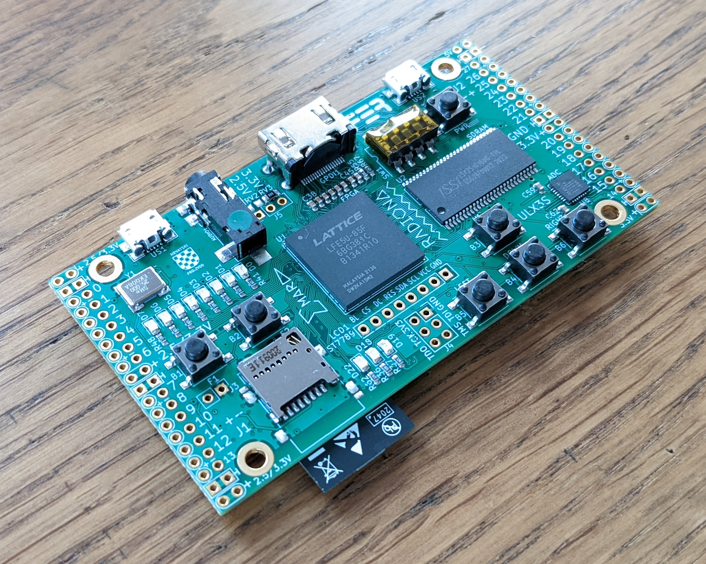
But sometimes you just wish to have some more resources on hand to get for example a VexRiscv based SoC running. That's why I had already eyeballed the ULX3S. After some delays due to production and the overall situation (chip shortage) I am now a proud owner of the ULX3S with an ECP5 85F FPGA.
 |
 |
|---|---|
What a beauty.
The ULX3S is OSHW. This means the schematics and layout for the board are available together with a lot of documentation and example projects. Similar for the iCE40 series the ECP5 series also has ongoing Open Source tooling support.
Specs
You can get the full specs from the official website.
Here I list the ones which were interesting for me:
- FPGA: Lattice ECP5 LFE5U-85F-6BG381C (84K LUT)
- One USB connected to a FTDI FT231XS and another USB connected directly to the FPGA
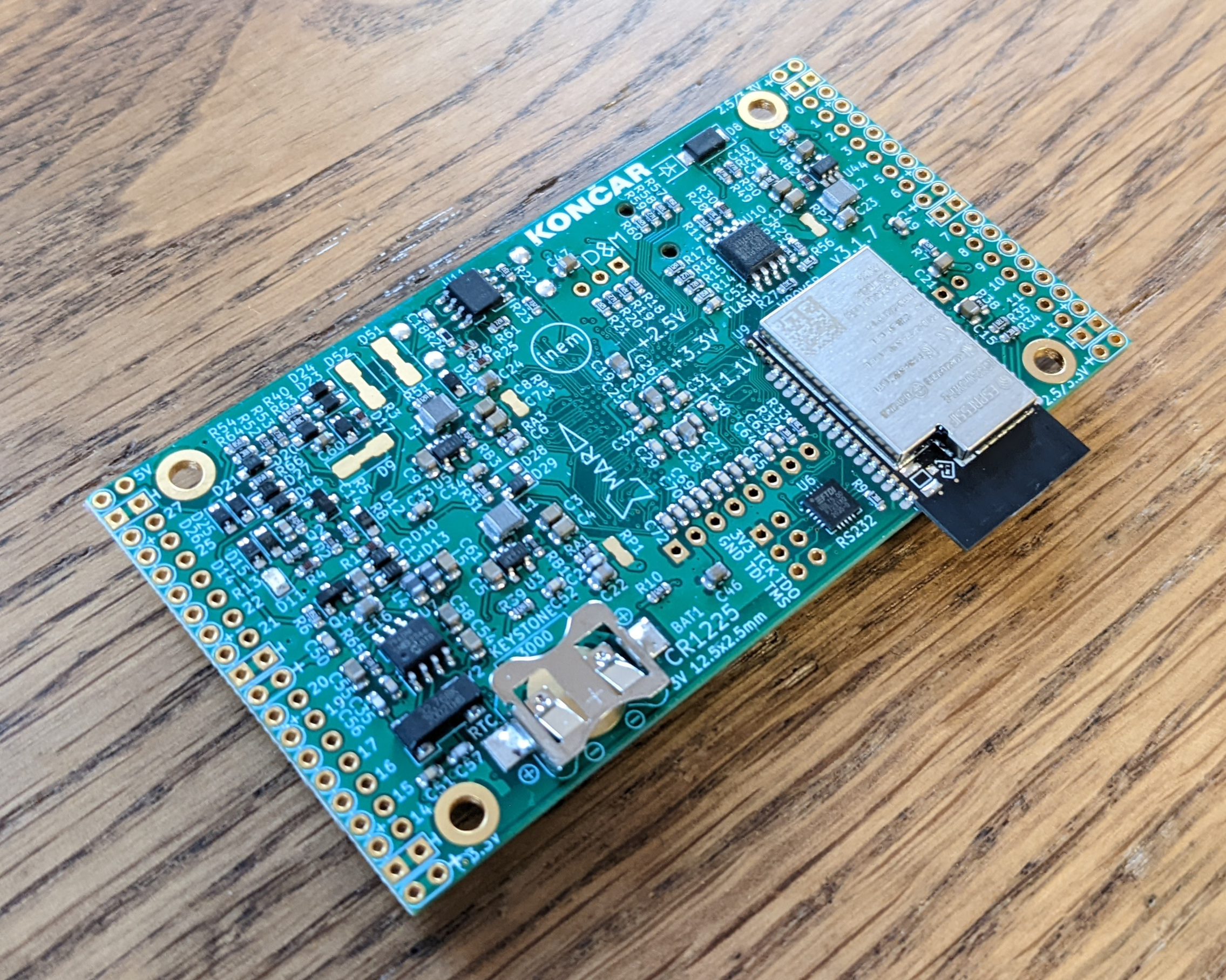
- WiFi through the ESP-32
- Peripherals
- buttons
- switches
- LEDs
- display placeholder
- Storage
- 32MB SDRAM 166 MHz
- 16MB Quad-SPI Flash
- Micro-SD slot
- Audio: 3.5 mm jack
- Digital video GPDI
- ADC 8 channels, 12 bit, 1 MSa/s
- PMOD compatible pinout
There are for sure a lot of things you can already do just with this board alone. Especially USB stuff is going to be interesting for me. If you happen to have exhausted all of the peripherals and interfaces on this device then you can always plugin some PMODs.
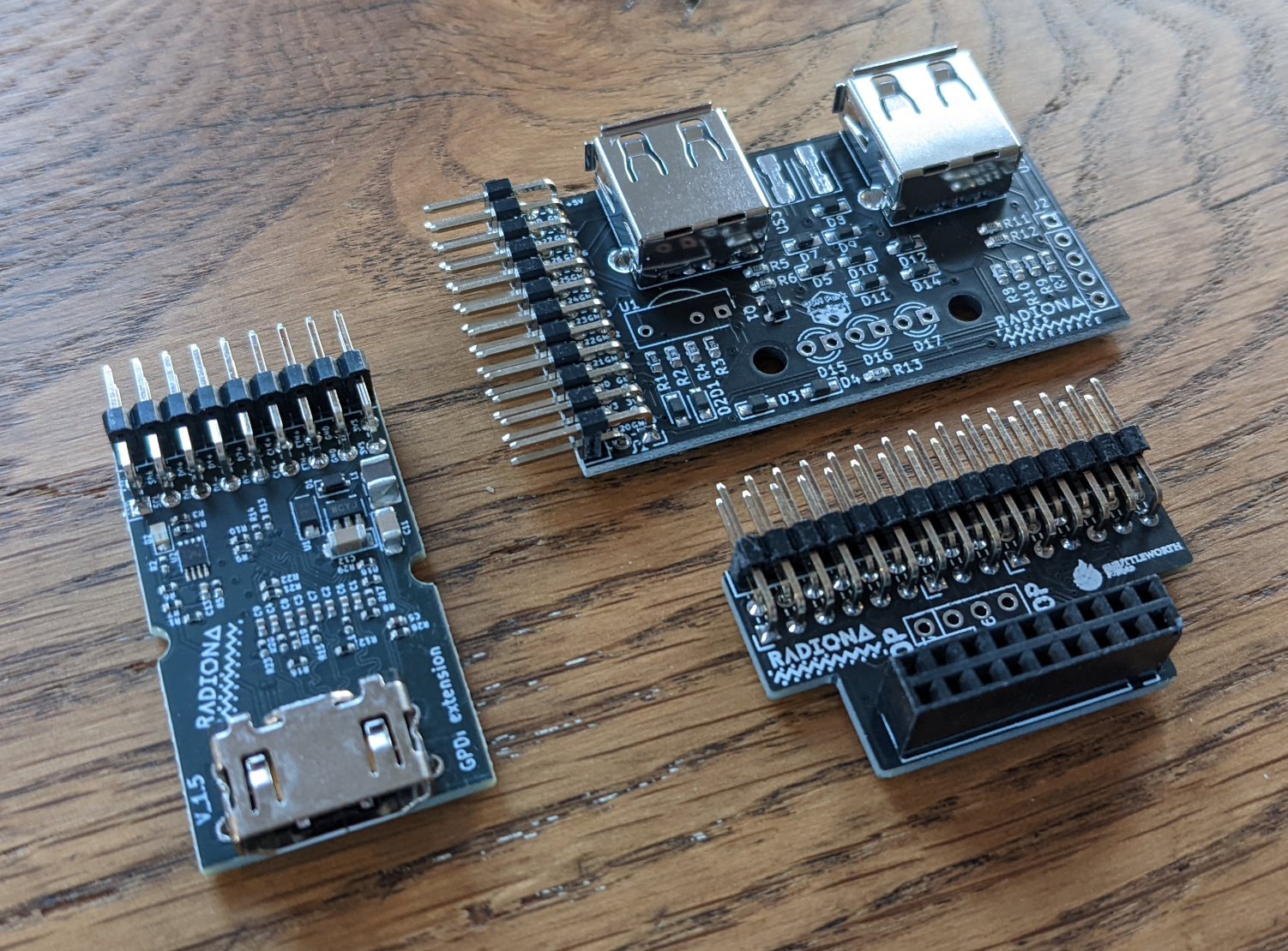
I also bought the official expansion boards which provide:
- Dual USB-A receptacle (with IR send/receive to solder on)
- GPDI input or output
- OV7670 camera connector (camera not included)
The first "Blinky"
Tooling
Currently the Open Source tools change almost daily. You get a lot of improvements with the recent versions. To really have the newest version of the toolchain I decided to give the OSS CAD Suite a chance.
This suite is a collection of prebuilt binaries of all the great open source tools used in digital logic design.
Get the newest build from the oss-cad-suite-build GitHub repository under the Releases section.
After you have downloaded the file, unpack it. Now how to actually use the tools? I mean, I don't always want to specify the full path to the binaries.
Well, the solution for that is to add the oss-cad-suite directory to the PATH environment variable like this:
> export PATH="/path/to/oss-cad-suite/bin:$PATH"
Now whenever you type e.g. iverilog, first this directory will be searched for a matching binary and only if none is found, other places are searched.
Code
With that out of the way I started to adapt a simple blinky example I found here. It is already great as it is but I changed some things to have it more my way.
This Makefile is used for the complete flow: synthesis, place and route, generating the bitstream and uploading to the device.
default: prog

.PHONY: clean upload

blinky.json: blinky.sv
    yosys -p 'synth_ecp5 -top top -json $@' $^

ulx3s_out.config: blinky.json
    nextpnr-ecp5 --85k --json blinky.json \
        --lpf ulx3s_v20.lpf \
        --package CABGA381 \
        --textcfg ulx3s_out.config

ulx3s.bit: ulx3s_out.config
    ecppack ulx3s_out.config ulx3s.bit

prog: ulx3s.bit
    openFPGALoader --board=ulx3s ulx3s.bit

clean:
    rm -rf blinky.json ulx3s_out.config ulx3s.bit
Well, of course we also need a simple SystemVerilog design. So here is the top module for blinky.
module top (
    input  logic clk_25mhz,
    input  logic [6:0] btn,
    output logic [7:0] led,
    );

    localparam cnt_width = 32;
    logic [cnt_width-1:0] cnt = 0;

    always @(posedge clk_25mhz) begin
        if (btn[0] == 1) begin
            cnt <= cnt + 1;
        end
    end

    assign led[7:0] = cnt[25:18];
endmodule
This counter increases continuously, bits 25 to 18 are wired to the LEDs on the board. When you press button 0 the counter will stop increasing and you can see the current value.
You will also need a constraint file. So get ulx3s_v20.lpf from here.
Upload
Before I could program the board I had to add a udev rule for the ULX3S. I followed the official manual for that.
Just create a new file:
> sudo touch /etc/udev/rules.d/80-fpga-ulx3s.rules
And fill it with this content:
# this is for usb-serial tty device
SUBSYSTEM=="tty", ATTRS{idVendor}=="0403", ATTRS{idProduct}=="6015", \
  MODE="664", GROUP="dialout"
# this is for ujprog libusb access
ATTRS{idVendor}=="0403", ATTRS{idProduct}=="6015", \
  GROUP="dialout", MODE="666"
Now just run the Makefile:
> make
Soon enough I had my ULX3S blinking!
Summary
I can't describe how glad I am that I don't need to download a vendor locked-in toolchain, tens of gigabytes in size just to get a simple blinky to run.
But the more important point: These tools are Open Source. They are developed by the community and some very talented people. They will stay this way no matter what, because the source code is open. They will get ported to other architectures (e.g. RISC-V) and you don't need to worry about not having access to them one day.
The speed of the entire workflow is simply incredible. Calling make with no prebuilt files completes in just a few seconds with this blinky:
real    0m6,687s
user    0m2,189s
sys     0m0,261s
Keep in mind that most of the time was spent uploading the bitstream to the device.
Now back to the board: The ULX3S is a great device with a wide range of peripherals and a lot of resources. I am going to use this device for exciting things!