Programming SPI NOR-FLASH
Introduction
If you read my previous post, you already know that I designed an FPGA dev board using Lattice's iCE40UP5k. The special thing about it is that I left out the FTDI chip that is responsible for programming the FPGA and the SPI FLASH.
So how do I get my bitstream into the FLASH? I have to program it with an external programmer. (There will be an easier way to load bitstreams, as I will explain in another blog post.)
So got me a TL866II Plus "Universal Programmer" that is capable of addressing many different targets, including SPI NOR-FLASH chips - exactly what we want.
Software
The programmer itself is completely proprietary - the firmware it comes with and the software that controls it.
Fortunately, there is an effort to create an open source program to control the MiniPRO TL866xx series of chip programmers: minipro.
So I compiled minipro from source and ran it. But before I can program a chip, I have to update the programmers firmware to the latest version supported by minipro.
Firmware Update
The firmware comes with the Windows software Xgpro. You can find a mirror of it at XGecu_Software.
In my case I navigated to Xgpro/12/ and downloaded
xgproV1250_setup.rar. Apply unrar twice to get to the files inside the .exe.
> unrar x XgproV1250_Setup.rar
> unrar x XgproV1250_Setup.exe
There you will find the file updateII.dat which is the firmware for the programmer.
Now we will use minipro to update the programmer:
minipro -F updateII.dat
Found TL866II+ 04.2.132 (0x284)
/path/to/updateII.dat contains firmware version 4.2.132

Do you want to continue with firmware update? y/n:
(I have already 04.2.132 running as I have updated before)
Enter y to update the firmware. Now we are ready to program the SPI FLASH.
Target Chip - Winbond W25Q128JVSIM
The chip in question is the W25Q128JVSIM SPI NOR-FLASH from Winbond. It has 8 pins and we can try to use the autodetect function from the programmer got get the exact device name.
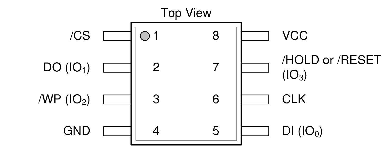 Pinout - taken from datasheet
The command to auto detect devices with 8 pins:
minipro --auto_detect 8
Found TL866II+ 04.2.132 (0x284)
Speicherzugriffsfehler
Segmentation fault (in German), well this did not work... I will open a bug report.
Let's try to specify the chip directly anyway. In the chip database I found W25Q128JV@SOIC8, which is exactly our chip.
Let's find out its ID:
> minipro -p W25Q128JV@SOIC8 -D
Found TL866II+ 04.2.132 (0x284)
Chip ID mismatch: expected 0xEF4018, got 0xFFFFFF (unknown)
Hm, we have an ID mismatch, because we received 0xFFFFFF. This usually means we have a bad connection.
Solving Problems
At first I tried to program the chip standalone by using clip to connect to the programmer. I suspected that the clip is faulty somehow, so I soldered the chip onto the FPGA dev board and used the header to connect it to the programmer.

This worked much better:
> minipro -p W25Q128JV@SOIC8 -D
Found TL866II+ 04.2.132 (0x284)
Chip ID mismatch: expected 0xEF4018, got 0xEF7018 (unknown)
But still there is an ID mismatch.
I had a quick look at the datasheet and it seems to be the correct ID:
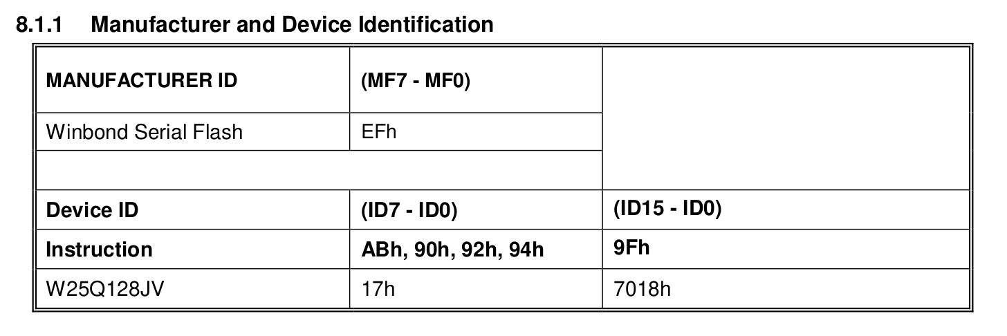 Manufacturer and Device Identification - taken from datasheet
Let's try to move on anyways by supplying -y to minipro.
Programming and Reading
I prepared an example bitstream for the FPGA to write to FLASH, read from FLASH, and compare to the original file.
The file is called test.bit.
> shasum test.bit
b9003c18c735e8b35df5541876b7f52f1498b3fc test.bit
> ls -al test.bit
-rw-r--r-- 1 leo leo 104090 3. Mär 09:24 test.bit
The size of it is 104090 bytes.
Let's write the file to the SPI FLASH:
> minipro -p W25Q128JV@SOIC8 -w test.bit -y -s
Here we need the -s flag because the file is smaller than the size of the flash (16777216 Bytes).
Found TL866II+ 04.2.132 (0x284)
WARNING: Chip ID mismatch: expected 0xEF4018, got 0xEF7018 (unknown)
Warning: Incorrect file size: 104090 (needed 16777216)
Erasing... 39.44Sec OK
Writing Code...  0.62Sec  OK
Reading Code...  0.18Sec  OK
Verification OK
This is very promising. The verification step reads the chip contents and verifies that the data was written correctly.
Always check for yourself! Let's read the content of the FLASH:
> minipro -p W25Q128JV@SOIC8 --read read.bin -y
Found TL866II+ 04.2.132 (0x284)
WARNING: Chip ID mismatch: expected 0xEF4018, got 0xEF7018 (unknown)
Reading Code...  26.65Sec  OK
Great! read.bin is now a 16.8 MB big file because we read the whole chip. If you look at the file with a hex editor, you will see some content at the beginning of the file, but after that it is all 0xFF. Why is this the case? When NOR-FLASH is erased all bits are set to 1.
Let's compare the checksum! First truncate read.bin to the same size as test.bit as we are only interested in the bitstream that we have written.
> truncate -s 104090 read.bin

> shasum read.bin
b9003c18c735e8b35df5541876b7f52f1498b3fc read.bin
It's the same value! We have successfully programmed our first SPI NOR-FLASH chip.
Summary
Not everything was straightforward on our journey - first a software bug, then a hardware error, and finally the ID mismatch. And still we managed to program the FLASH!
I will open an issue report for the segmentation error in the repository for minipro.
But for now we are done, as I have everything I need to continue with the bring up of the FPGA dev board.